Wednesday, June 25, 2008

VRay System


VRay System

General

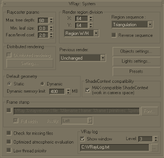
In this section you can control variety of VRay parameters. These are divided into the following sections:

Parameters

Raycaster parameters

Here you can control various parameters of VRay's Binary Space Partitioning (BSP) tree.

One of the basic operations that VRay must perform is raycasting - determining if a given ray intersects any geometry in the scene, and if so - identifying that geometry. The simplest way to implement this would be to test the ray against every single render primitive (triangle) in the scene. Obviously, in scenes with thousands or millions of triangles this is going to be very slow. To speed this process, VRay organizes the scene geometry into a special data structure, called a binary space partitioning (BSP) tree.

The BSP tree is a hierarchical data structure, built by subdividing the scene in two parts, then looking at each of those two parts and subdividing them in turn, if necessary and so on. Those "parts" are called nodes of the tree. At the top of the hierarchy is the root node - which represents the bounding box of the whole scene; at the bottom of the hierarchy are the leaf nodes - they contain references to actual triangles from the scene.

Max tree depth - the maximum depth of the tree. Larger values will cause VRay to take more memory, but the rendering will be faster - up to some critical point. Values beyond that critical point (which is different for every scene) will start to slow things down. Smaller values for this parameter will cause the BSP tree to take less memory, but rendering will be slower.

Min leaf size - the minimum size of a leaf node. Normally this is set to 0.0, which means that VRay will subdivide the scene geometry regardless of the scene size. By setting this to a different value, you can make VRay to quit subdividing, if the size of a node is below a given value.

Face/level coef - controls the maximum amount of triangles in a leaf node. If this value is lower, rendering will be faster, but the BSP tree will take more memory - up to some critical point (which is different for every scene). Values below that critical point will make the rendering slower.

Default geometry - internally VRay maintains four raycasting engines. All of them are built around the idea of a BSP tree, but have different uses. The engines can be grouped into raycasters for non-motion blurred and for motion blurred geometry, as well as for static and dynamic geometry. This parameter determines the type of geometry for standard 3dsmax objects. Note that some objects (displacement-mapped objects, VRayProxy and VRayFur objects, for example) always generate dynamic geometry.

Static geometry is precompiled into an acceleration structure at the beginning of the rendering and remains there until the end of the frame. Note that static raycasters are not limited in any way and will consume as much memory as necessary.

Dynamic geometry is loaded and unloaded on the fly depending on which part of the scene is being rendered. The total memory taken up by the dynamic raycasters can be controlled within certain limits.

Dynamic memory limit - the total RAM limit for the dynamic raycasters. Note that this limit is divided between the number of rendering threads. If you specify 400 MB total limit, for example, and you have a dual processor machine with multithreading enabled, then each rendering thread will use 200 MB for its dynamic raycaster. If this limit is too low, and geometry needs to be loaded and unloaded very often, this may turn out to be slower than rendering in single-threaded mode.

Render region division

Here you can control various parameters of VRay's rendering regions (buckets). The bucket is an essential part of the distributed rendering system of VRay. A bucket is a rectangular part of the currently rendered frame that is rendered independently from other buckets. Buckets can be sent to idle LAN machines for processing and/or can be distributed between several CPUs. Because a bucket can be processed only by a single processor the division of the frame in too small a number of buckets can prevent the optimal utilization of computational resources (some CPUs stay idle all the time). However the division of the frame in too many buckets can slow down the rendering because there is a some time overhead related with each bucket (bucket setup, LAN transfer, etc).

X - determines the maximum region width in pixels (Region W/H is selected) or the number of regions in the horizontal direction (when Region Count is selected)

Y - determines the maximum region height in pixels (Region W/H is selected) or the number of regions in the vertical direction (when Region Count is selected)

Region sequence - determines the order in which the regions are rendered. Note that the default Triangulation sequence is best if you use a lof of dynamic geometry (displacement-mapped objects, VRayProxy or VRayFur objects), since it walks through the image in a very consistent manner so that geometry that was generated for previous buckets can be used for the next buckets. The other sequences tend to jump from one end of the image to another which is not good with dynamic geometry.

Reverse sequence - reverses the Region sequence order

Note: When the Image Sampler is set to Adaptive Sampler the size of the buckets will be rounded up to the nearest number which is a power of 2.

Previous render

This parameter determines what should be done with the previous image in the virtual frame buffer when rendering starts. The possible values are:

Unchanged - no changes will be made - the virtual frame buffer remains the same;

Cross - every second pixel of the image will be set to black;

Fields - every other line of the image will be set to black;

Darken - the colors in the image will be darkened.

Note that this parameter has no effect on the final result of the rendering; it is implemented simply as a convenient way to distinguish between parts from the current frame being rendered, and part left over from the previous rendering.

Distributed rendering

Distributed rendering is the process of computing a single image over several different machines. Note that this is different from distributing the frame over several CPU's in a single machine, which is called multithreading. VRay supports multithreading, as well as distributed rendering.

Before you can use the distributed rendering option, you must determine the machines that will take part in the computations. Both 3dsmax and VRay need to be properly installed on those machines, although they don't need to be authorized. You must make sure that the VRay spawner application is running on those machines - either as a service, or as a stand-alone application. Refer to the Installation section for more details on configuring and running the VRay spawner.

For additional information on distributed rendering, please refer to the dedicated Distributed rendering section.

Distributed rendering - this checkbox specifies whether VRay will use distributed rendering.

Settings... - this button opens the VRay Networking settings dialog. See the Distributed rendering section for more information.

ShadeContext compatibility

VRay carries all its computations in world space. However, some 3dsmax plugins (notably atmospherics) take it as granted that the renderer works in camera space, because this is what the default scanline renderer does. To preserve compatibility with such plugins, VRay emulates work in camera space by converting the various points and vectors passed to and from other plugins.

In addition to slowing down VRay by forcing it to convert values all the time, working in camera space messes up with camera modifiers such as the Technical camera script. This why you have the option of turning off the camera-space emulation.

Frame stamp

The frame stamp is a convenient way to put some short text over the rendered images. It can be useful in many ways - for example, in network rendering, to quickly determine which frames were rendered by which machine. The frame stamp is one line of text, which appears at the bottom of the image.

Checkbox - turns the frame stamp on and off.

Edit box - here you enter the text you wish to appear in the images. You can also use some special keywords, all of which begin with the percent symbol (%). The keywords are replaced by VRay with the corresponding value:

Keyword Meaning
%vrayversion the current version of VRay
%filename the name of the current scene file
%frame the number of the current frame
%primitives * the number of unique intersectable primitives generated for the current frame*
%rendertime the render time for the current frame
%computername the network name of the computer
%date the current system date
%time the current system time
%w the width of the image in pixels
%h the height of the image in pixels
%camera the name of the camera for this frame (if rendering from a camera, empty string otherwise)
% the value of any VRay parameter, given its MaxScript name (see section on MaxScript)
%ram the amount of physical memory (in KBytes) installed on the system
%vmem the amount of virtual memory (in KBytes) available on the system
%mhz the clock speed of the system CPU(s)
%os the operating system

* An intersectable primitive is a primitive that provides a direct method for intersection with a ray (such as a triangle, the infinite plane generated by a VRayPlane plugin etc). Most often, the number of these primitives is the same as the number of triangles (faces) processed by VRay for the current frame. Note that this may be different from the total number of triangles in the scene. With the dynamic raycaster, only geometry that is actually needed is generated and accounted for. Geometry that is not generated is not included in this count.

Font - this button allows you to choose a font and font attributes for the text in the frame stamp.

Full width - when this option is checked, the frame stamp will take the whole width of the image, otherwise the stamp will be only as wide as the text is.

Justify - specifies the position of the stamp:

Left - the stamp is placed on the left of the image.

Center - the stamp is centered.

Right - the stamp is placed on the right side of the image.

Object Settings / Light Settings

These buttons bring up the dialogs for the local object and light settings.

Presets

This button brings up the presets dialog.


VRay Camera


VRay Camera

General

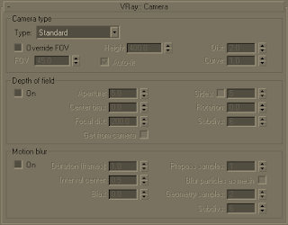
The camera rollout controls the way the scene geometry is projected onto the image.

Parameters

Camera type


The cameras in VRay generally define the rays that are cast into the scene, which essentially is how the scene is projected onto the screen. VRay supports several camera types: Standard, Spherical, Cylindrical (point), Cylindrical (ortho), Box and Fish eye. Orthographic views are supported too.

Override FOV - with this setting you can override the 3dsmax's FOV angle. This is because some VRay camera types can take FOV ranges from 0 to 360 degrees, whereas the cameras in 3dsmax are limited to 180 degrees.

FOV - here you specify the FOV angle (only when Override FOV is turned on and the current camera type supports FOV angle).

Height - here you can specify the height of the Cylindrical (ortho) camera. Note: this setting is available only when the Type is set to Cylindrical (ortho).

Auto-fit - this setting controls the auto-fit option of the Fish-eye camera. When Auto-fit is enabled VRay will calculate the Dist value automatically so that the rendered image fits horizontally with the image's dimensions.

Dist - this setting applies only to the Fish-eye camera. The Fish-eye camera is simulated as a Standard camera pointed to an absolutely reflective sphere (with a radius of 1.0) that reflects the scene into the camera's shutter. The Dist value contorts how far is the camera from the sphere's center (which is how much of the sphere will be captured by the camera). Note: this setting has no effect when the Auto-fit option is enabled.

Curve - this setting applies only to the Fish-eye camera. This setting contorts the way the rendered image is warped. A value of 1.0 corresponds to a real world Fish-eye camera. As the value approaches 0.0 the warping is increased. As the value approaches 2.0 the warping is reduced. Note: in fact this value controls the angle at which rays are reflected by the virtual sphere of the camera.

Type - from this list you can select the type of the camera. The available types are Standard, Spherical, Cylindrical (point), Cylindrical (ortho), Box, Fish eye. See the Examples section for a more detailed discussion on camera types.

Standard - this is a standard pinhole camera.

Spherical - this is a spherical camera which means that the camera lenses has spherical form.

Cylindrical (point) - with this type of camera all rays have a common origin - they are cast from the center of the cylinder. In the vertical direction the camera acts as a pinhole camera and in the horizontal direction it acts as a spherical camera.

Cylindrical (ortho) - in vertical direction the camera acts as an orthographic view and in the horizontal direction it acts as a spherical camera.

Box - the box camera is simply 6 standard cameras placed on the sides of a box. This type of camera is excellent for generation of environment maps for cube mapping. It may be very useful for GI too - you can calculate the irradiance map with a Box camera, save it to file and you can reuse it with a Standard camera that can be pointed at any direction.

Fish eye - this special type of camera captures the scene as if it is normal pinhole camera pointed at an absolutely reflective sphere which reflects the scene into the camera's shutter. You can use the Dist/FOV settings to control what part of the sphere will be captured by the camera. The red arc in the diagram corresponds to the FOV angle. Note that the sphere has always a radius of 1.0.

Depth of field

On - turns the depth-of-field effect on.

Aperture - this is the size of the virtual camera aperture, in world units. Small aperture sizes reduce the DOF effect, larger sizes produce more blur.

Center bias - this determines the uniformity of the DOF effect. A value of 0.0 means that light passes uniformly through the aperture. Positive values mean that light is concentrated towards the rim of the aperture, while negative values concentrate light at the center.

Focal distance - determines the distance from the camera at which objects will be in perfect focus. Objects closer or farther than that distance will be blurred.

Get from camera - when this option is on, the Focal distance is determined from the camera target, if the rendering is done from a camera view.

Sides - this option allows you to simulate the polygonal shape of the aperture of real-world cameras. When this option is off, the shape is assumed to be perfectly circular.

Rotation - specifies the orientation of the aperture shape.

Anisotropy - this option allows the stretching of the bokeh effect horizontally or vertically. Positive values stretch the effect in the vertical direction. Negative values stretch it in the horizontal direction.

Subdivs - controls the quality of the DOF effect. Lower values are computed faster, but produce more noise in the image. Higher values smooth out the noise, but take more time to render. Note that the quality of sampling also depends on the settings of the QMC sampler as well as on the chosen Image sampler.

Motion blur

On - turns motion blur on.

Duration - specifies the duration, in frames, during which the camera shutter is open.

Interval center - specifies the middle of the motion blur interval with respect to the 3dsmax frame. A value of 0.5 means that the middle of the motion blur interval is halfway between the frames. A value of 0.0 means that the middle of the interval is at the exact frame position.

Bias - this controls the bias of the motion blur effect. A value of 0.0 means that the light passes uniformly during the whole motion blur interval. Positive values mean that light is concentrated towards the end of the interval, while negative values concentrate light towards the beginning.

Prepass samples - this controls how many samples in time will be computed during irradiance map calculations.

Blur particles as mesh - this option controls the blurring of particle systems. When this is on, particles will be blurred like normal meshes. However, many particle systems change the number of particles between frames. You can turn off this option to compute the motion blur from the velocity of the particles instead.

Geometry samples - this determines the number of geometry segments used to approximate motion blur. Objects are assumed to move linearly between geometry samples. For fast rotating objects, you need to increase this to get correct motion blur. Note that more geometry samples increase the memory consumption, since more geometry copies are kept in memory.

Subdivs - determines the quality of the motion blur. Lower values are computed faster, but produce more noise in the image. Higher values smooth out the noise, but take more time to render. Note that the quality of sampling also depends on the settings of the QMC sampler as well as on the chosen Image sampler.

Notes

  • Depth of field is supported only for the Standard camera type. Other camera types do not produce depth of field effect at this time.
  • When DOF and motion blur are both enabled, they are sampled together using the higher of the two Subdivs parameters.

VRay Default Displacement


VRay Default Displacement

General

This section allows you to control displacement of objects with displacement materials, which do not have a VRayDisplacementMod modifier applied.

Parameters

Override Max's - when this option is on, VRay will render objects with displacement materials using its own internal microtriangle displacement. When this option is off, the objects will be rendered with the standard 3dsmax displacement.

Edge length - this determines the quality of the displacement. Each triangle of the original mesh is subdivided into a number of subtriangles. More subtriangles mean more detail in the displacement, slower rendering times and more RAM usage. Less subtriangles mean less detail, faster rendering and less RAM. The meaning of Edge length depends on the View-dependent parameter below.

View-dependent - when this is on, Edge length determines the maximum length of a subtriangle edge, in pixels. A value of 1.0 means that the longest edge of each subtriangle will be about one pixel long when projected on the screen. When View-dependent is off, Edge length is the maximum subtriangle edge length in world units.

Max. subdivs - this controls the maximum subtriangles generated from any triangle of the original mesh. The value is in fact the square root of the maximum number of subtriangles. For example, a value of 256 means that at most 256 x 256 = 65536 subtriangles will be generated for any given original triangle. It is not a good idea to keep this value very high. If you need to use higher values, it will be better to tesselate the original mesh itself into smaller triangles instead. From build 1.45.20 onward, the actual subdivisions for a triangle are rounded up to the nearest power of two (this makes it easier to avoid gaps because of different tesselation on neighboring triangles).

Tight bounds - when this is on, VRay will try to compute the exact bounding volume of the displaced triangles from the original mesh. This requires pre-sampling of the displacement texture, but the rendering will be faster, if the texture has large black or white areas. However, if the displacement texture is slow to evaluate and varies a lot between full black and white, if may be faster to turn this option off. When it is off, VRay will assume worst-case bounding volumes, and will not presample the texture.

Notes

  • The default displacement amount is based on the bounding box of an object. Therefore, it is not a good choice when you have deforming objects. In that case, you should apply a VRayDisplacementMod modifier, which supports constant displacement amount.

VRay Color Mapping


Ray Color Mapping

Search keywords: color mapping, tone mapping, burn-out, overexpose

General

Color mapping (also called tone mapping) can be used to apply color transformations on the final image colors. Sometimes an image can contain a higher range of colors that can be displayed on a computer screen. Color mapping has the task of re-mapping the image values to be suitable for display purposes.

Parameters

Type - this is the type of transformation used. These are the possible types:

Linear multiply - this mode will simply multiply the final image colors based on their brightness are. Color components that are too bright (above 1.0 or 255) will be clipped. This can result in burnt out spots near bright light sources.

Exponential - this mode will saturate the colors based on their brightness. This can be useful to prevent burn-outs in very bright areas (for example around light sources etc). This mode will not clip bright colors, but will instead saturate them.

HSV exponential - this mode is very similar to the Exponential mode, but it will preserve the color hue and saturation, instead of washing out the color towards white.

Intensity exponential - this mode is similar to the Exponential one, but it will preserve the ratio of the RGB color components and will only affect the intensity of the colors.

Gamma correction - this mode applies a gamma curve to the colors. In this case, the Dark multiplier is a general multiplier for the colors before they are gamma-corrected. The Bright multiplier is the inverse of the gamma value (f.e. for gamma 2.2, the Bright multiplier must be 0.4545).

Intensity gamma - this mode applies a gamma curve to the intensity of the colors, instead of each channel (r/g/b) independently.

Reinhard - this mode is a blend between exponential-style color mapping and linear mapping. If the Burn value is 1.0, the result is linear color mapping and if the Burn value is 0.0, the result is exponential-style mapping.

Dark multiplier - this is the multiplier for dark colors.

Bright multiplier - this is the multiplier for bright colors.

Gamma - this parameter allows the user to control the gamma correction for the output image regardless of the color mapping mode. Note that the value here is the inverse of the one used for the Gamma correction color mapping type. For example, to correct the image for a 2.2-gamma display, you should set the Gamma parameter simply to 2.2.

Sub-pixel mapping - this option controls whether color mapping will be applied to the final image pixels, or to the individual sub-pixel samples. In older versions of VRay, this option was always assumed to be on, however its default value is now off as this produces more correct renderings, especially if you use the universal settings approach.

Affect background - if this is off, color mapping will not affect colors belonging to the background.

Clamp output - if this is on, colors will be clamped after color mapping. In some situations, this may be undesirable (for example, if you wish to antialias hdr parts of the image, too) - in that case, turn clamping off.

VRay Environment

VRay Environment

General

The Environment section in VRay render parameters is where you can specify a color and a map to be used during GI and reflection/refraction calculations. If you don't specify a color/map then the MAX's background color and map will be used instead.

Parameters

GI Environment (skylight)


This group allows you to override the 3dsmax Environment settings for indirect illumination calculations. The effect of changing the GI environment is similar to skylight.

Override MAX's - with this option turned on VRay will use the specified environment color and/or texture during GI calculations.

Color - lets you specify the background (skylight) color.

Multiplier - a multiplier for the color value. Note that the multiplier does not affect the environment texture (if present). Use an Output map to control the brightness of the environment map if the map itself does not have brightness controls.

Texture - lets you choose a background texture.

Reflection/refraction environment

This group allows you to override the 3dsmax Environment settings when reflections and refractions are calculated. Note that you can also override the reflection/refraction environment on a per material basis (see VRayMtl) or a per map basis (see VRayMap).

Override MAX's - with this option turned on VRay will use the specified Color and Texture during GI and reflection/refraction calculations.

Color - lets you specify the background (skylight) color.

Multiplier - a multiplier for the color value. Note that the multiplier does not affect the environment texture (if present). Use an Output map to control the brightness of the environment map, if the map itself does not have brightness controls.

Texture - lets you choose a background texture

VRay Caustics


VRay Caustics

General

VRay supports the rendering of the caustics effects. In order to produce this effect you must have proper caustics generators and caustics receivers in the scene (for information how to make an object a caustics generator/receiver read the Object settings and Lights settings sections in Render parameters > System > Object/Light settings. The settings in this parameter section control the generation of the photon map (an explanation of the photon map can be found in the Terminology section).

Parameters

On - turns caustic on and off.

Multiplier - this multiplier controls the strength of the caustics. It is global and applies to all light sources that generate caustics. If you want different multipliers for the different light sources then you should use the local light settings. Note: this multiplier is cumulative with the multipliers in the local light settings.

Search dist - when VRay traces a photon that hits an object in some point the raytracer searches for other photons on the same plane in the surrounding area (search area). The search area in fact is a circle with center the original photon and its radius is equal to the Search dist value.

Max photons - when VRay traces a photon that hits an object in some point and counts the photons in the surrounding area it then averages the illumination of that area based on the number of the photons in it. If the photons are more than Max photons VRay will only take the first Max photons of them.

Max density - this parameter allows you to limit the resolution (and this the memory) of the photon map. Whenever VRay needs to store a new photon in the caustics photon map, it will first look if there are any other photons within a distance specified by Max density. If there is already a suitable photon in the map, VRay will just add the energy of the new photon to the one in the map. Otherwise, VRay will store the new photon in the photon map. Using this options allows you to shoot many photons (and thus get smoother results) while keeping the size of the caustics photon map manageable.

Mode - controls the mode of the irradiance map:

New map - when this option is selected a new photon map will be generated. It will overwrite any previous photon map left over from previous rendering.

Save to file - hit this button if you want to save an already generated photon map in a file.

From file - when you enable this option VRay will not compute the photon map but will load it from a file. Hit the Browse button on the right to specify the file name.

Don't delete - when checked, VRay will keep the photon map in memory after the scene rendering has finished. Otherwise the map will be deleted and the memory it takes will be freed. This option can be especially useful if you want to compute the photon map for a particular scene only once and then reuse it for further rendering.

Auto save - when this is turned on, VRay will automatically save the caustics photon map to the provided file when rendering is complete.

Switch to saved map - this option is only available if Auto save is on. It will cause VRay to automatically set the mode to From file with the file name of the newly saved map.

Notes

Caustics also depend on th

VRay rQMC Sampler


VRay rQMC Sampler

General

rQMC (randomized Quasi Monte Carlo) sampling is employed throughout VRay for every "blurry" value - antialiasing, depth of field, indirect illumination, area lights, glossy reflection/refraction, translucency, motion blur etc. rQMC sampling is used to determine what samples should be taken and, ultimately, which rays to trace.

Instead of having separate methods for sampling each of those blurry values, VRay has a single unified framework that determines how many and what exactly samples to be taken for a particular value, depending on the context in which that value is required. This framework is called the rQMC sampler.

Note that although similar in concept, the sampling method employed by VRay is different from strict QMC sampling in that the number sequences that are used have higher discrepancy than pure QMC methods (but still lower one compared to pure random Monte Carlo methods).

The actual number of samples for any blurry value is determined based on three factors:

  • The subdivs value supplied by the user for a particular blurry effect. This is multiplied by the Global subdivs multiplier (see below).
  • The importance of the value (for example, dark glossy reflections can do with fewer samples than bright ones, since the effect of the reflection on the final result is smaller; distant area lights require fewer samples than closer ones etc). Basing the number of samples allocated for a value on importance is called importance sampling.
  • The variance (think "noise") of the samples taken for a particular value - if the samples are not very different from each other, then the value can do with fewer samples; if the samples are very different, then a larger number of them will be necessary to get a good result. This basically works by looking at the samples as they are computed one by one and deciding, after each new sample, if more samples are required. This technique is called early termination or adaptive sampling.

For more information on the relationship and effects of these parameters, please refer to the tutorials section.

Parameters


Amount - controls the extent to which the number of samples depends on the importance of a blurry value. It also controls the minimum number of samples that will be taken. A value of 1.0 means full adaptation; a value of 0.0 means no adaptation.

Min samples - determines the minimum number of samples that must be made before the early termination algorithm is used. Higher values will slow things down but will make the early termination algorithm more reliable.

Noise threshold - controls VRay's judgment of when a blurry value is "good enough" to be used. This directly translates to noise in the result. Smaller values mean less noise, more samples and higher quality. A value of 0.0 means that no adaptation will be performed.

Global subdivs multiplier - this will multiply all subdivs values everywhere during rendering; you can use this to quickly increase/decrease sampling quality everywhere. This affects everything, except for the lightmap, photon map, caustics and aa subdivs. Everything else (dof, moblur, irradiance map, qmc GI, area lights, area shadows, glossy reflections/refractions) is affected by this parameter.

Time independent - when this option is On, the rQMC pattern will be the same from frame to frame in an animation. Since this may be undesirable in some cases, you can turn this option Off to make the rQMC pattern change with time. Note that re-rendering the same frame will produce the same result in both cases.